Wednesday 20 May 2015

The quest for the perfect gradient.

I often have to create linear or radial gradients to use as masks or UV input. I’ve always created them in photoshop using the gradient tool and I’ve always been frustrated by the fact that you cannot place them numerically.
Today I’m rolling up my sleeves and I’m going to sort this out instead of grumbling internally.

This might seem a bit extreme but this sort of issue gets on my nerves if I encounter them every single time.

Case study 1: Photoshop and the gradient tool.


My problem is: I’m eyeballing it. The snapping doesn’t work on the gradient tool so I have to use the grid or some guides and zoom in as much as possible to try and be accurate but I cannot guarantee I’m not a couple of pixels off.

I can prove myself it’s not perfect however. It’s subtle but look at the gif below (yes it’s animated I promise). I’ve flipped the ramp horizontally and vertically, and you can see it jump back and forth a few pixels. I’m not happy.


Case study 2: Photoshop again


I asked our UI guy for advice and he uses layer styles to create gradients.


Nice one. It’s editable, you can modify it at will and the align with layer makes it clean and fully accurate.
But hang on, what does the flipping test tell us? Dammit! Still not perfect!


Case study 3: Illustrator


I normally have a thing for illustrator, just like after effects. All that numerically placing everything and oh my, those smart guides… They’re just heaven.
But in this case Illustrator the Great disappointed me. The gradient tool is very neat, the UI is clear, contextual just where need be and super clever as usual but the smart guides don’t work with it. Shame on you Illustrator. I just have to leave you there.
(I still appreciate that your gradient can be either edited numerically in the gradient window or intuitively on the fly with the mouse cursor.)


Case study 4: After effects


Aaah, shape layers. What a bliss.
The gradient fill won’t disappoint you. The shape layer path will define the bounds, you can tweak the start / end positions on top of it using the well-named start and end options, and the whole gradient is editable.


Yet there again, the flipping test shows that the gradient is not perfectly centred. I’m starting to see a pattern here. Could it be I am asking for the moon?


Case study 5: Substance


I'm lucky enough to know a beta tester so I was able to quickly try it in substance. I definitely want to spend more time with substance which looks mind blowing but I’m still very limited with using it right now.
Using the Tile_generator with a paraboloid pattern type I was able to create a radial gradient. I have no control over the shape of the gradient with that option. There are obviously much better ways of doing it but that was the easiest way to test quickly it. 

 
And you know what ? It flips perfectly. Tadaaa.


Conclusion.                                                                           

 I thought about it for a second and it hit me. I always work with power of two textures. If I’ve got a 128*128 texture, surely that’s great caus’ my centre is at 0. Yeah but no. With any adobe method, it looks like the gradient won’t start in between two pixels. It needs a pixel to use as a centre, it seems. I tried it on a 129*129 square and the flipping would leave the gradient unchanged.
I suppose substance handled it better because the creation of the gradient comes from maths rather than a tool.


Epilogue.

Unfortunately, substance isn't part of my day-to-day workflow. I hope it will some day.
I currently go with the Photoshop gradient overlay layer styles for all my gradients. If I use the gradient tool to create a gradient and want to modify it months later but I've forgotten to save it, then I'm screwed and I have to try and recreate it. The layer styles mean my gradient always remains editable.


Monday 20 April 2015

Mapping a texture to world coordinates. Part 5.

Example 4: texturing an object.


Finally, to close this topic here's a little experiment.
When powers or magic are involved, you will often face the issue of having to overlay some FX material on characters although their UVs were not designed for it. What you want is your Fx UVs to be independent from the textured model's.

You could animate your material in screen space. That's not too bad an option but that'll be visible as the camera and the animated models move.

You could create a second UVs set with cylindrical UV mapping. This is the method I used on the doppelganger model in DmC 5 DLC: Vergil Downfall.
 
That comes at a cost (that of an extra UVS set) and depending on the shape of your model, you can experience some stretching in certain areas. (It was mostly ok on that slim character but still not fully satisfying).


Another method would be to have a material that is not UV dependant but that would still move with the object.
I can't guarantee this is production worthy, I only made it for fun. It might be too expensive to actually be usable but I still like the idea. 

This is a capture of the first test I made… wow, almost two years ago already.

I'll recreate something similar now. (I wish I had saved my packages at the time.)
We'll start it simple and gradually add layers of complexity.


Mapping each axis.

Right now we want to hide the result on the faces not pointing towards z. We'll check which direction the vertices are facing. Those that face z return a value of 1, the others of 0. (Sure, that's a bit simplified but it's ok for now since we're working with a cube.)

White and black? Yay we got ourselves a mask. We just need to multiply this with our remapped texture.


(Note that we use a scalar parameter to adjust the size, not just a constant. You'll use that same parameter on each axis so that the sizes are consistent. Besides, when comes the time for actually texturing an object it's better to adjust your values within a material instance than editing your original material.)


The value of the normal is -1 on the bottom. We use the abs node to make negative values absolute (that is to say, positive) and now we see both the top and bottom of the cube. 

  • We duplicate the above set up 3 times and tick the correct channels to appropriately map along x, y and z and then we add everything together. We can safely do so with nothing overlapping since we've only retained what's happening along a single axis every time.

Mis-ticking a box is easy. To double check that a section of material is fine you can right clic any node and go ‘Start previewing node’. Saves you the hassle of having to temporarily plug that bit in your output.


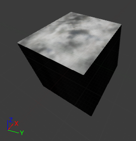
  • Here we go. We've got all our faces textured. 


It doesn't look like much so far, because it's only a cube but if you move it around you can see how the texture sort of belongs to the world. We're not using the UVs space so we could texture any object, not just a cube.

Like this chair for instance:


Making the material local.

If you want the object to be animated, it's not good to see it move through the texture. We'll make it local, as we did before.


Separating positive and negative axis.

We've got the basics in place. Now we want this material to look a bit more interesting.
We'll start by panning our texture.

Right now, the positive and negative axis display the same thing. Since we are pretending this is happening in space we need to invert the panning direction in positive and negative for the texture to appear to rotate around the object.

In order to get the positive and negative both white and the rest black, we've just made the vertex normal absolute. Now we're going to use a ceil node so that the positive axis is white and the rest is black. Then we can use the output as a mask.

When I want to check whether my connections are right, I often use a lerp with obvious colours. I might have mentioned this before, I'm not sure. 
With this we can double check that +x is green while rest is red (even the back, I promise you). We're good to go.

  • Here's the whole thing with the inverted panners in x and the ceiled result used as a mask to drive the linear interpolation:

Now, this works on a cube which normals conveniently face a single axis but that's not good on a sphere for instance. The textures projected along different axis overlap because each vertex is not just facing x, y or z. It's a bit of each.
We're going to need to modulate the transitions between our masks.
(Too many gifs, I'm dizzy. Oh, and by the way I'm changing to a more contrasted texture. I had picked a random one to start with.)

Transition between facing axis.

On a very smooth object such as a sphere, the normals are not going to get to a full 0 until they reach the next axis. That's why you can see the textures overlap.
Here is the preview of one single texture. In this case, you would want to see the texture on the sides, but not all the way to the front.
 
  • We'll just add a power on what we use as a mask: after the abs on the vertex normals that is.

Power of 1 (same as no power):

Power of 5:

We replicate this for each axis, only this time we're renaming the parameter to have a different control for x, y and z. We'll need different adjustments per axis depending on our object.

Here's the result on a sphere. The x and y work ok, the z not so much because its panning speed can't match in every direction. We'll leave it as is for now.
Now I want to start making some actual art. To do so more easily I want to be able to control my parameters from a material instance. That material is too spread out to work from inside.

My problem is, I've got the texture's scale exposed but not its panning speed. I would like to be able to control the speed in x and y independently but I can't do so right now.
You see, both my x and y panning values are contained within the same panner. If I multiply time, both x and y will be affected the same. And I can't multiply time by a vector 2 constant because the panner expects a constant 1 time input. We'll need to make more changes to our material.


Controlling x and y panning speed from the material instance.

Here's a simple way of splitting both speeds:
Just link two panners in a row. The first one has a speed of x = 1, y = 0, the second one is x = 0 , y = 1.


Now for the complicated one.
Why so? Because I built it before I realised I had a very simple and easy option and I don't want my hard work wasted. Besides, as it turns it seems to be 2 instructions cheaper according to the material editor stats.

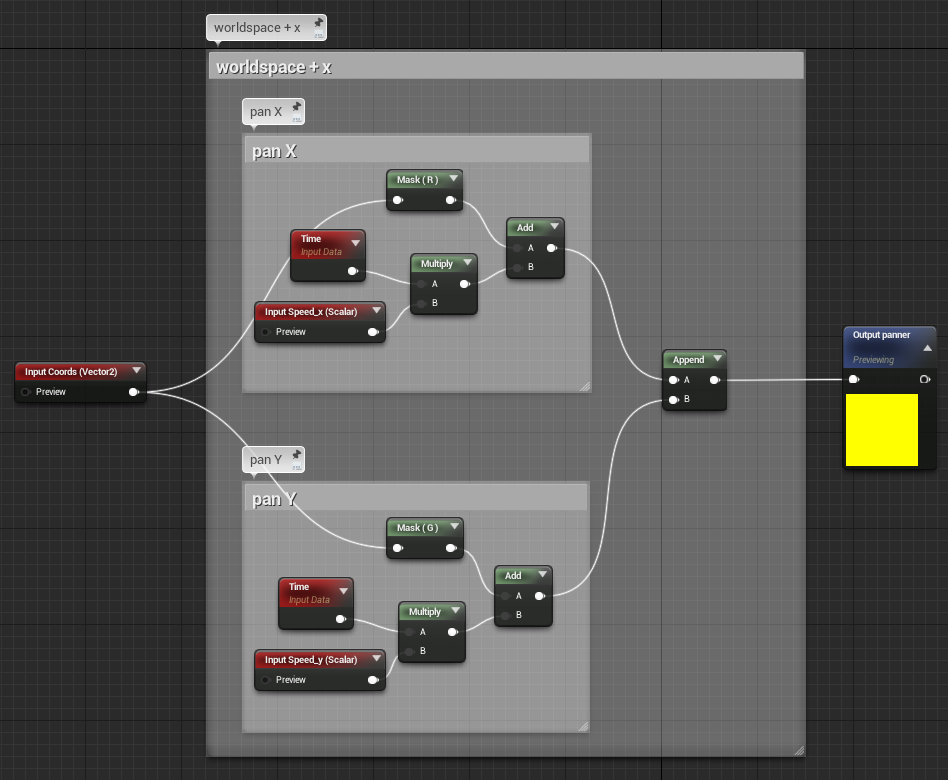
Basically, we'll recreate the functionality of a panner. Panning is adding a value to our coordinates to shift them over time. We'll just do that: add time to our coordinates.
In the following screenshot, the input coming from off screen on the left are the coordinates in world space. We filter them and keep only the x or y, and add time that is multiplied by a parameter to which we'll have access in the material instance. Easy enough.

The only problem is: it looks kinda messy. Well not messy but big. Way too big. We need controls over x and y for the vertices facing worldspace x and an inverted speed for the vertices facing worldspace -x. Even though we can reuse the block controlling the y speed it's still a lot of nodes.
And that's where some cool guys come into play:


Material functions.

We'll make a function out of this. A material function is a bunch of instructions you put together and nestle within a single node to keep things neat and easily propagate changes. You can use a material function in any given material. 
I won't go in depth on how to make one, it's all in the documentation, I don't think I'd have anything to add to it, but feel free to ask questions if you have any.

Here's my function:
I've got several exposed parameters; three inputs:
- texture coordinates
- speed x
- speed y
And a single output: that'll be the coordinates going through the panners.


Here's the function used twice to replace our groups of nodes. I didn't have to duplicate the ‘speed y’ parameter but I like to avoid connections crossing.
You see:
Much clearer isn't it?


Finally, here's the whole thing:


Arted example.

With the above screenshot you've got the basis to make the material work. Now I'll make an arted version but this will only be one of the possible outcomes. You could imagine doing anything you usually do with a texture to make this more interesting.

My advice would be: don't get too carried away because this thing can quickly scale up and get out of hands.

Before you go too far with this and add a lot of details, preview it in actual game conditions. If there's a lot of action / post processes / particles going on, if that material doesn't stay on for too long, if you don't have any slomo involved… well a simple version is probably enough. The patterns of a couple of moving textures can be spotted quite easily if you stare at them but perhaps a player won't be staring and it'll just be parts of his landscape. It really depends on the context of your game.


Looking back at my old video capture, I was probably multiplying an animated texture with a mask.
The choice I've made this time is to pan a texture and offset its UVs with two panning textures added together. Don't pay attention to the model itself, it's a default example model from zbrush.


The transitions are seamless, our previous issue with the z axis not matching is not visible so I basically ignored it and didn't try to fix it. (This means I can simplify the material and remove the bits about inverting the panning direction for the z axis by the way.)


You can see that this happens in world space, not in UV space since I can scale the model without the texture scaling along.

And with this, our topic is wrapped up at last !

Wednesday 25 February 2015

Mapping a texture to world coordinates. Part 4.


Example 3: Starry night

Now, this is a little experiment I run over a year ago as I got started with UE4 vector fields. I wanted to create an animated version of Van Gogh's famous painting ‘Starry Night’ with GPU particles.
I hand painted the vector field in maya, created a flat initial location box (same ratio as the painting's), and thousands of small rectangular particles followed the vector field. As they moved, they would pick the colour of the painting used as a texture mapped in world space.

I was really quite happy with this idea but it turned out that someone had already created this as an app and they'd done a good job of it. Once I found out it seemed pointless to complete the project. Great minds think alike, they say. Fair enough but really, you wanna be the first of those minds.
Oh well, nevermind. I still had some good fun doing the tests plus it gives me an example for you people to enjoy.

So. We have the dimensions we want the painting to be displayed at, and we want them to be translated to texture coordinates. I've decided I'd keep the centre of the painting in the middle; I could have decided for it to be in a corner, I would just have had to use different values for the min and max.


Here's what's happening in the material: I'm ‘projecting’ the texture in world space (as seen in the first part) and making its coordinates local (as seen previously), and then I use my favourite little snippet (described here) to remap the 0 to 1 texture coordinates to the size I want the texture to appear in world units.


Then in cascade I create a box with an initial location that matches my min and max and as the sprites move, they pick the colour of the painting underneath.
It's rather basic, close up you can see it is a cut out and it doesn't feel like moving paint strokes. I was thinking of trying to see if I could use the ParticleSpeed to offset the texture but as I said I gave up on the project quite early on.
Painting this vector field again in maya has actually been very interesting, it's going to be helpful for my personal project. I've found out a few things about how to get a vector field UE4 ready. I'll keep that for a later post, still lots I don't know about.

This is a capture of the animated particles in cascade preview: (for those who don't know, cascade is the name of unreal's particle editor)


If I place this emitter in the world, and I add more particles around my initial location area, you can see how the last pixels are stretched. It shows that the texture is mapped to a precise area in space (centered around the emitter position).

Same thing from the side, the pixels are stretched because we only projected along one axis.


Hope you enjoyed this, folks. The next and last example will actually be my favourite one, so stay tuned.

Sunday 25 January 2015

Mapping a texture to world coordinates. Part 3.

Example 2: laser effect


------------------------------- Distorting UVs -------------------------------

To start with, quick digression for beginners: 

If you want to animate a texture, the setup is very similar. Instead of plugging your distortion texture directly into the output texture, you add it to your texture coordinates beforehand.

What does that mean? Adding a value to texture coordinates means you are shifting the pixels around. 1 is the width and height of your texture.

Take a horizontal line.
Add 0 to it, it stays in place.
Add 0.5 to it, it moves to the top edge.
Add 1 to it, it appears to have stayed in place but really, it's been all around and back to its original position.


In the next example, I use a gradient from black to a 0.5 grey:


Reminders:
- Don't forget that the distortion texture should be linear (= not Srgb) if you're after a mathematically correct result.(I first made the mistake here and wondered why the result wasn't as exected.)
- You don't have to use black and white textures; you can use two channels to shift the U and V independently. Just use a component mask because UV info requires 2 channels while the RGB of a map is 3.


So. This is what you get from plugging directly the distortion texture in the output texture:

This is what you get from adding the distortion texture to texture coordinates before plugging it in the output texture:
 (note that I've reduced the influence of the distortion)

And this the animated preview: 

I've been through this quite quickly since we've kinda covered it before and most of you probably know this in and out. Don't hesitate if you have questions.


------------------------------- End of the digression -------------------------------


Now to our example.
Months ago I starting talking about mapping a texture using the world space rather than the UV space.

Here's a second example.
Say you've got a moving object which projects a laser that reveals the smoke in the air. We want our laser material to fake the fact it is lighting some smoke.
Now that I think about it, it might sound a bit previous gen, what with lit particles in every engine nowadays. Still I'll stick to this example because there can be more than one use to a principle. (and because I already spent a few hours on this!)

Whichever way the object moves, the smoke should remain static. You do not want the smoke material to be mapped to the UVs of your geometry or sprite. It should be mapped to the world where it supposedly belongs.

The moving object in my example is actually… fictional. Yes, you have to imagine it, all I've done is the ‘laser’. Which is not much of a laser in the end. I didn’t want to spend too much time polishing something which is not going to be used anywhere so I essentially stuck to the showcase of what this post is about: mapping textures to world space coordinates. I’ll keep the frills and glamour for some other day. (maybe)

Now, what do we have here?
A normal map is used twice (normal 1 and normal 2 boxes), mapped to world coordinates with different scales and panning at different speeds. They are brought together to use as a noise that will distort the UVs of another texture.
Usually you would add the result to a texture coordinates node. Since we are mapping our textures to the world, we’re using the world position setup instead, but the idea is exactly the same.

That goes into two different textures that get added together (all of that to add a bit of complexity so the patterns don't repeat too obviously) and into our output texture at last.


Finally, there you go:
The object moves in space and through the smoke.